Product / HSL
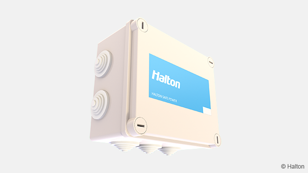
Halton Safe HSL – Link unit
Independent fire damper link unit to be connected to 1-4 fire dampers and 1-4 smoke detectors.
- Controlling fire dampers and smoke detectors in buildings.
Overview
Halton Safe HSL link unit is a part of Halton fire and smoke safety offering.
This is an independent fire damper link unit to be connected to 1-4 fire dampers and 1-4 smoke detectors.
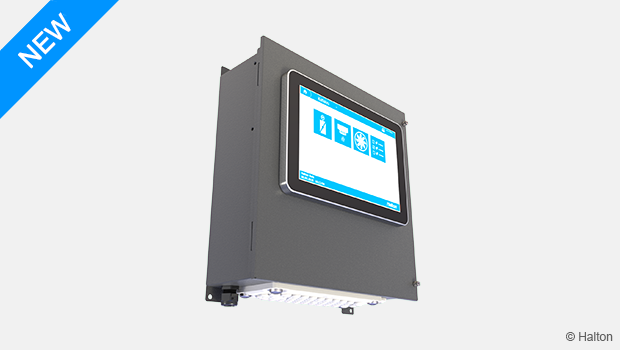
Halton Safe HSL link units use an internal communication bus to communicate with the Halton Safe Management 2.0 controller. The link units are programed from the Halton Safe Managenent 2.0 controller. Halton Safe HSL link unit contains a memory, which ensures that their settings are not lost even if the power supply to the system fails. If the connection to the controller is lost, the link units continue running independently.
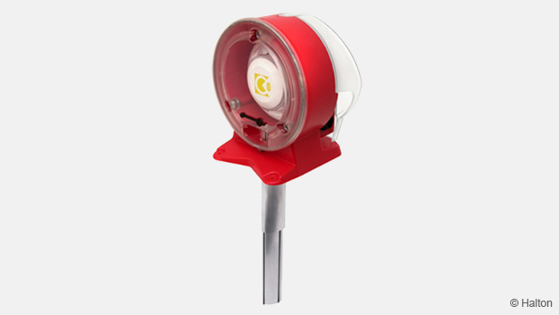
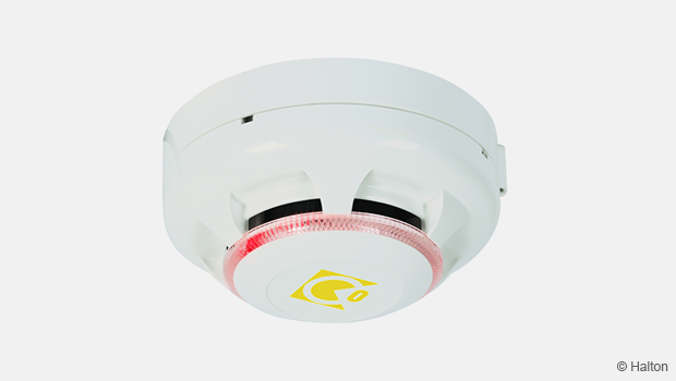
Halton Safe HSL link units include a 24 V DC power supply for smoke detectors. The system is designed to be used with the following types of smoke detectors: Halton Safe HSR, smoke sensor in room and Halton Safe HSD, smoke sensor in duct.
Applications
- Controlling fire dampers and smoke detectors in buildings.
Key features
- Can connect to 1-4 fire dampers
- Can connect to 1-4 smoke detectors
- Easy to install
Features and options
| Feature | Description |
| Power supply | 24 V AC |
| Fuse | SMD 2410 5 A F |
| Communication bus | Modbus RTU |
| IP class | IP55 |
Structure and components
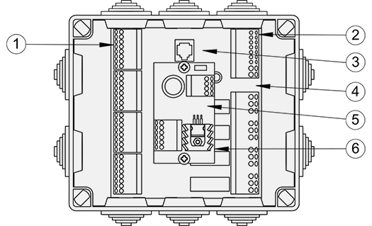
Fig.1. Structure of Halton Safe HSL
| No. | Part | Details |
| 1 | I/O terminals | Terminals for fire dampers and smoke detectors |
| 2 | Bus connections | Internal bus to Halton Safe Management 2.0 controller and Halton Safe HSL link units |
| 3 | Indicators for buscommunication | – |
| 4 | 24 V fuse | SMD 2410 5 A F |
| 5 | Power indicator | – |
| 6 | DC transformer | 24 W |
Dimensions and weight
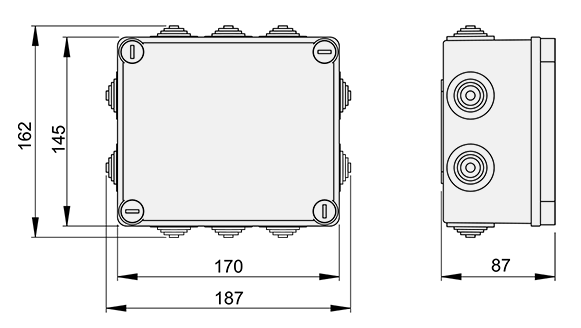
Fig.2. Dimensions of Halton Safe HSL
Weight:
1.5 kg
Specification
Link unit for fire dampers and smoke detectors in the Halton Safe Management 2.0 system.
Installation information
Connection diagram
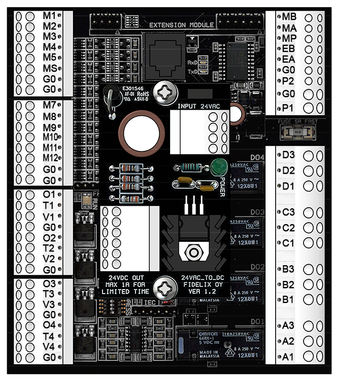
Fig.3. Connection diagram of Halton Safe HSL
Terminals
| Terminal | Actuator/sensor | Comment |
| M1 | S1 | Damper1 |
| M2 | S4 | Damper1 |
| M3 | 3/1 | Feedback from smoke detector 1 |
| M4 | S1 | Damper 2 |
| M5 | S4 | Damper 2 |
| M6 | 3/1 | Feedback from smoke detector 2 |
| G0 | S2, S6 | Damper 1 |
| G0 | S2, S6 | Damper 2 |
| Terminal | Actuator/sensor | Comment |
| M7 | S1 | Damper3 |
| M8 | S4 | Damper3 |
| M9 | 3/1 | Feedback from smoke detector 3 |
| M10 | S1 | Damper 4 |
| M11 | S4 | Damper 4 |
| M12 | 3/1 | Feedback from smoke detector 4 |
| G0 | S2, S6 | Damper 3 |
| G0 | S2, S6 | Damper 4 |
| Terminal | Actuator/sensor | Comment |
| O1 | – | Not in use |
| T1 | 2 | Power Damper 1 |
| V1 | 1 | Power Damper 1 |
| G0 | – | Not in use |
| O2 | – | Not in use |
| T2 | 2 | Power Damper 2 |
| V2 | 1 | Power Damper 1 |
| G0 | – | Not in use |
| Terminal | Actuator/sensor | Comment |
| O3 | – | Not in use |
| T3 | 2 | Power Damper 3 |
| V3 | 1 | Power Damper 3 |
| G0 | – | Not in use |
| O4 | – | Not in use |
| T4 | 2 | Power Damper 4 |
| V4 | 1 | Power Damper 4 |
| G0 | – | Not in use |
| Terminal | Actuator/sensor | Comment |
| MB | – | Internal bus, line B |
| MA | – | Internal bus, line A |
| MP | – | Not in use |
| EB | – | Not in use |
| EA | – | Not in use |
| G0 | – | Internal use |
| P2 | – | Internal use |
| G0 | – | Input power 24 V AC |
| P1 | – | Input power 24 V AC |
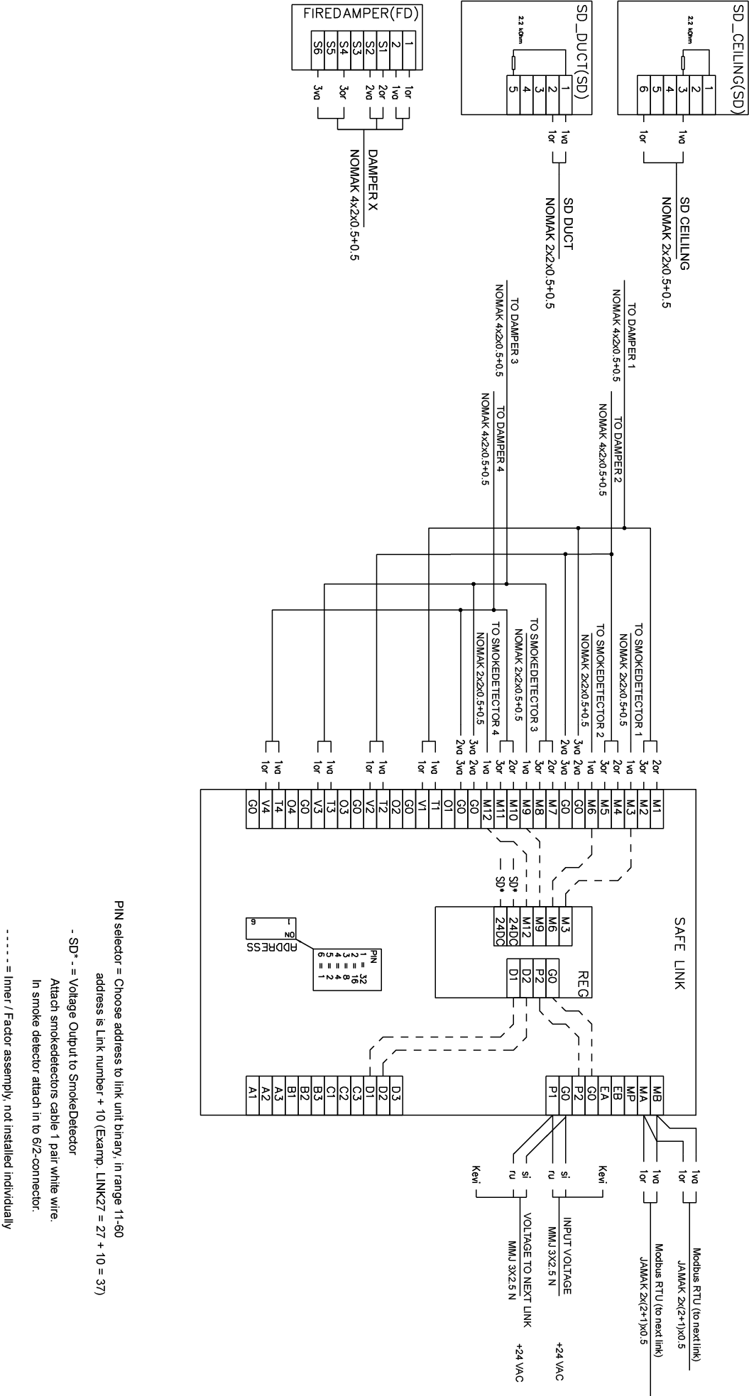
Fig.4. Wiring diagram of Halton Safe HSL
Order code
HSL; ZT
ZT = Tailored product
N No
Code example
HSL, ZT=N
Downloads
"*" indicates required fields