Product / PDA
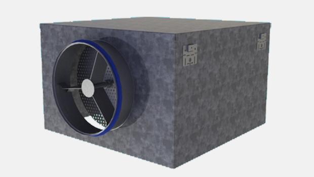
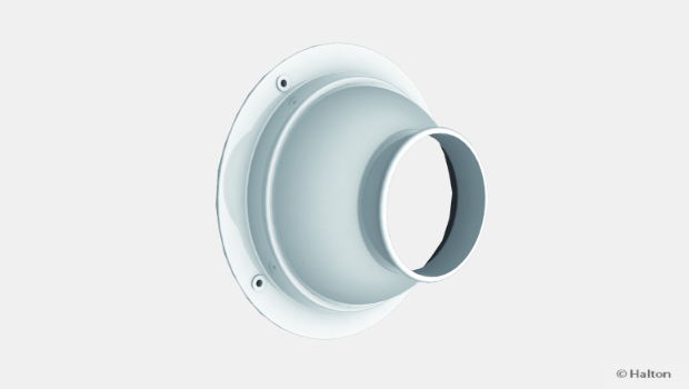
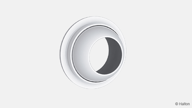
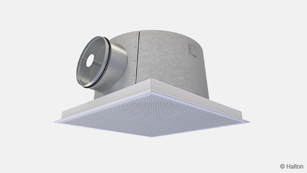
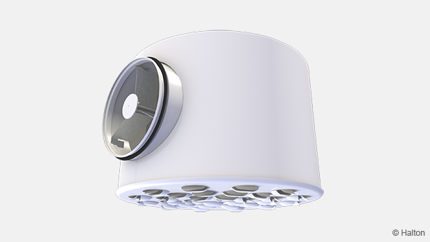
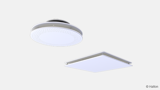
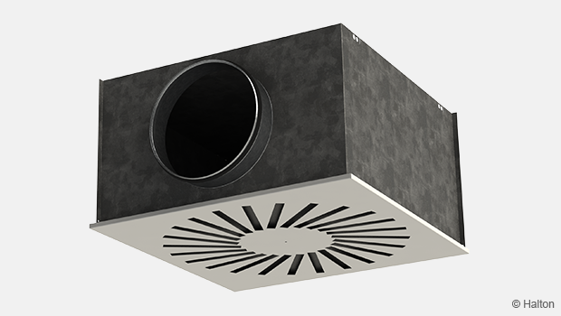
Halton PDA – Plenum for diffusers
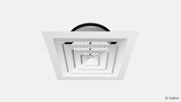
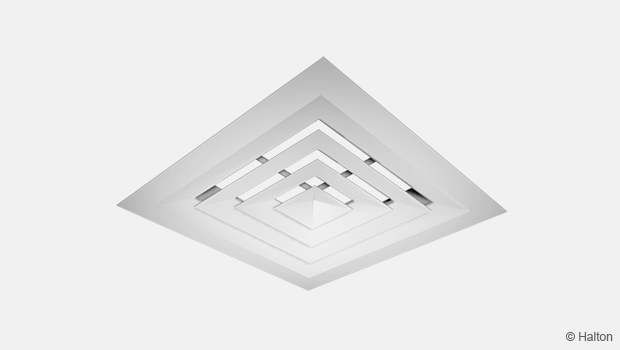
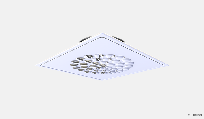
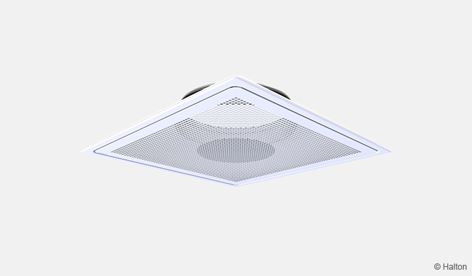
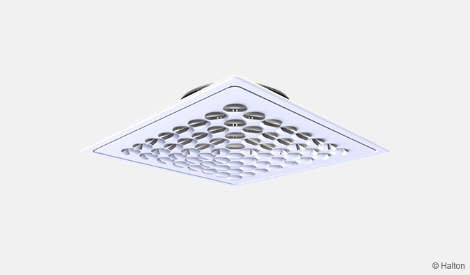
Plenum for Halton DAC diffuser
- Ensures proper function of the supply air diffuser
- Access for ductwork cleaning
Overview
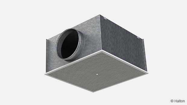
- Plenum for connecting Halton DAC diffuser (supply, exhaust,filtration) unit to ductwork
- Ensures proper function of the supply air diffuser
- Access for ductwork cleaning
Product Models and Accessories
- Model with sound attenuation material
- Detachable airflow rate measurement and balancing module available.
Dimensions
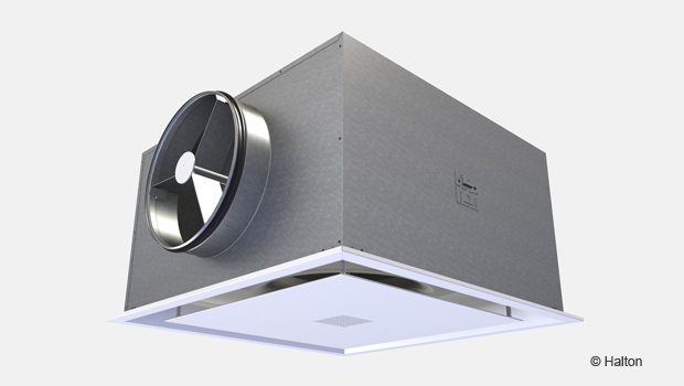
Halton PDA/H
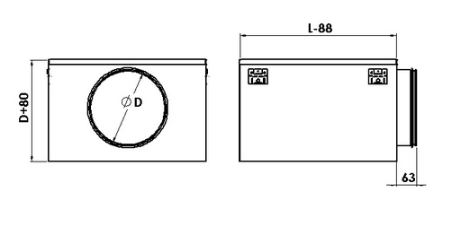
Note: For plenum model without filter (PDA/H-S and PDA/H-R), the height is reduced to D+50
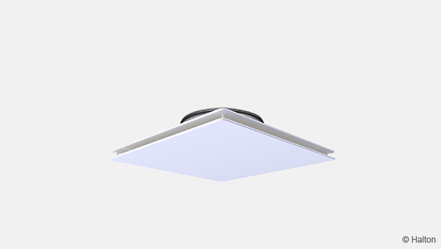
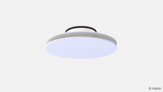
Halton PDA/V
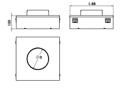
| NS | L |
| 600×600 | 595 |
| 675×675 | 670 |
Material
| Part | Material | Note |
| Plenum box / spigot | Galvanised steel | |
| Sound attenuation material | Mineral wool | The mineral wool is fixed with nails |
| Filter | Media G3 |
Accessories
| Accessory | Code | Description |
| Sound attenuation material | IN | Mineral wool in the Halton PDA/H on 2 sides (IN=2) |
| Sound attenuation material | IN | Mineral wool in the Halton PDA/H on 5 sides (IN=5) |
| Sound attenuation material | IN | Mineral wool in the Halton PDA/V on 4 sides (IN=5) |
| Airflow measurement and adjustment unit |
OM | For supply installation |
Function
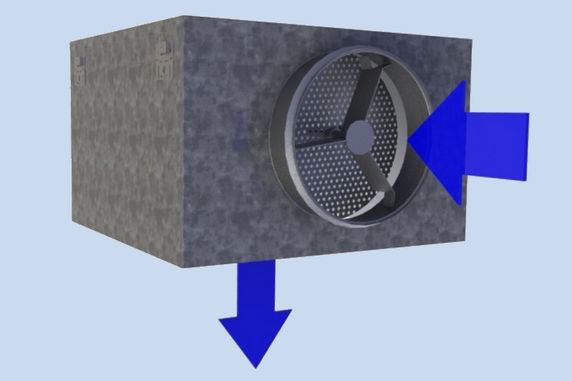
The duct pressure and air velocity are reduced inside the Halton PDA plenum box
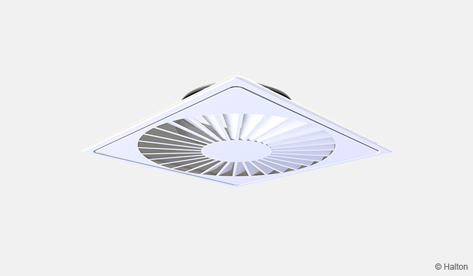
Air is supplied into the space through the diffuser, improving the air distribution quality and the noise level.
The airflow rate can be adjusted using the optional measurement and adjustment module MSM.
Installation
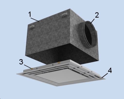
Key:
1. Plenum
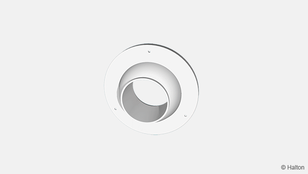
2. Spigot
3. Clips
4. Front plate
Plenum installation
The plenum is installed into the suspended ceiling with M8 drop rods (not supplied in the delivery) and connected to the ductwork with a spigot.
When equipped with a measurement and adjustment module, the recommended safety distance upstream of the device is at least 3xD, in order to ensure a reliable airflow rate measurement.
The units control spindle must not be excessively bent.
Diffuser installation
For integral diffusers with 600×600 tiles, the diffuser is attached to the plenum via clips.
For integral diffusers with 675×675 tiles, the diffuser is attached to the plenum with screws or pop rivets (not supplied).
Adjustment
To aid in adjusting and measuring the airflow rate, it is recommended that the diffuser is connected to a plenum equipped with a MSM.
The supply airflow is determined by measuring the pressure difference with a measurement module.
Measure the differential pressure with a manometer. The airflow rate is calculated according to the following formula:
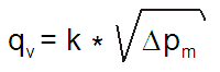
∆pm Measured pressure [Pa]
k k factor given as a function of mounting and diameter
qv Airflow rate [l/s]
The k factor for installations with different safety distances
(distance of other items from the MSM):
| Safety distance | ||
| Spigot Diameter | > 6xD | min 3xD |
| 200 | 28 | 32 |
| 250 | 49 | 51 |
| 315 | 78 | – |
Adjust the airflow rate by rotating the control spindle until the desired setting is achieved.
Lock the damper in position with a screw.
Replace the tubes and spindle in the plenum, and return the diffuser to its position.
Servicing
Supply and exhaust without filter
Detach the diffuser, clean the parts by wiping with a damp cloth.
Push the diffuser back into place by clipping the plenum.
Exhaust with filter
Activate the push-pull system by pressing on the diffusers’ front panel.
Open the front panel and rotate 90°.
Rotate the brackets 90°, and pull out the filter.
Install a new filter in the same position, close the front panel by pressing the push-pull release.
Option: MSM
Remove the measurement and adjustment module by gently pulling the shaft; (not the control spindle or measurement tubes!).
Wipe the parts with a damp cloth, instead of immersing in water.
Reassemble the measurement and adjustment module by pushing the shaft back into place until the module meets the stopper.
Push the diffuser back into place.
Specifications
The plenum is made of galvanised steel.
The plenum comprises an airflow measurement and adjustment module.
The plenum comprises sound attenuation material made of mineral wool.
The plenum reduces duct pressure and air velocity in order to supply air throughout the entire face area of the Halton DAC diffuser and improve the air distribution quality and the noise level.
Order Code
PDA/S-C-XXX-D; IN-OM-ZT
S = Configuration
V Vertical
H Horizontal
C = Application
S Supply
R Return
F Filtration (opening front)
XXX = False ceiling dimensions
600 600×600
700 675×675
D = Diameter of duct connection
200, 250, 315
Other Options and Accessories
IN = Insulation
2 2 face insulation (PDA/H)
4 4 face insulation (PDA/V)
5 5 face insulation (PDA/H)
OM = MSM
N No
Y Yes
ZT = Tailored product
N No
Y Yes
Code Example
PDA/V-S-600-200,IN=4,ON=Y,ZT=N
Downloads
"*" indicates required fields
Halton APL – Jet air diffuser
product
Halton APS – Jet air diffuser
product
Halton BCF – Floor diffuser
product
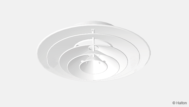
Halton CAR – Conical diffuser
product
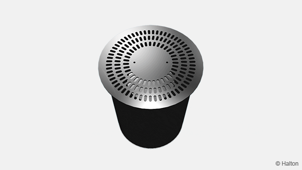
Halton DAC – Square diffuser
product
Halton DCS – Modular diffuser
product
Halton DFA – Square conical diffuser
product
Halton DFB – Conical diffuser
product
Halton DRV – Multi-nozzle terminal unit
product
Halton IAO – Jet nozzle diffuser
product
Halton Jaz JCC – Diffuser
product
Halton Jaz JDA – Diffuser with side slot
product
Halton Jaz JDB – Diffuser with side slot
product
Halton Jaz JDS – Variable air volume diffuser unit (VAV)
product
Halton Jaz JMC – Nozzle diffuser
product
Halton Jaz JRC – Perforated diffuser
product
Halton Jaz JRP – Swirl diffuser
product
Halton Jaz JSC – Nozzle diffuser
product
Halton Jaz JTH – Swirl diffuser
product
Halton Jaz JWC – Swirl diffuser
product